User Tools
Table of Contents
Alternators can be used as motors.
How To
- Get an alternator from a junkyard (or pay for a new one on ebay, rockauto.com, etc.)
(If anyone has pictures/model numbers/car models and years, please contribute here.) CS130D Phantom 48 used a GM alternator. Phantom ICT uses a bigger one.
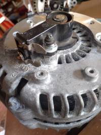
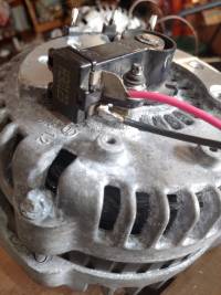
- Remove the regulator. (Unbolt)
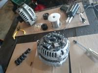
- Solder some RC style bullet connectors on to the three windings.
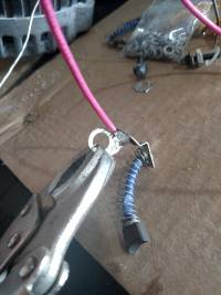
- Solder wires onto the contacts for the brushes to drive the field windings.
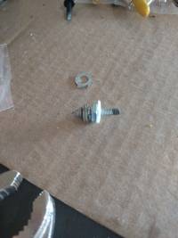
- Isolate the brushes from the case with nylon washers, bolts, or by clipping the metal so it doesn't touch.
- Reassemble
- Get a controller.1500W
- Get a field drive (Constant Current). DC-DC Buck Converter Step Down Regulator 60V 48V 36V 24V 12V to 19V 14V 9V 6V 3V
- Carefully set the field to about 3-4A with a screwdriver. (Start at lowest voltage/current and carefully work your way up with both a current meter and voltage meter to monitor your progress)
- Drive!
Extra credit:
- Field weakening.
Someone add notes here, because I've never actually done it on a car with any success. You basically have it run less current to the field once you hit top speed, and then you can go faster.
- Field strengthening. Some cars do this. They have a button that increases the current to the field. The button basically puts more current into the field so that you have more torque to start from a stop (at the start of the race, etc.
Notes from Facebook group discussions
(David Ortiz-Grob) First stop: get that 1500w motor controller that’s like $34 (Jared McNeil)
this one: https://www.ebay.com/.../48V-DC-1500W.../252876629480… EBAY.COM 48V DC 1500W Brushless Motor Controller For E-bike Scooter…
(Craig Byrne) Is there an agreed upon field winding voltage range yet? Or if it needs to be dynamic depending on throttle? (Jared McNeil) the way i understand it is that field current is more important than field voltage, and that it should be right around 4 Amps continually from startup all the way up until your max speed. THEN it is optionally dynamic (but only in the lessening direction) to further your top-end.
Jared McNeil we ran with a 12V4A field coil on a bench test with success Iacona Andrew What do you use to make the field
Craig Byrne Basically, take the cap off an alternator and remove the diode pack., you'll either find 3 wires of 6 wires on the outer windings. If it's 6 make them into 3 consecutive pairs. Then take apart the part where the brushes contact the “commutator” you'll need to apply voltage to this to make the the the shaft an electromagnet. This replaces the permanent magnet in other brushless motors.
Jared McNeil this isn't the best video in the world but it goes over a bit about how to make those changes: https://www.youtube.com/watch?v=IKqy3rRWJQE
YOUTUBE.COM Converting a Car Alternator into a Go Kart Motor
Iacona Andrew I watched it seems to skip a lot of things
Jared McNeil yeah there's some more content i found about it when i was researching about how to do it also and idk if i can find it again
Iacona Andrew Also does the size matter? Car, truck etc
David Ortiz-Grob David Ortiz-Grob Bigger is better obvs but there’s no straightforward way to convert the rated generation voltage and current into usable motor power
(Not entirely true. The big alternators on Phantom ICT seem to draw a lot of current just spinning themselves with no load. Whereas the smaller ones on Phantom 48 seem to have a lower current draw. This matters due to the fuse limit.)
Murray Hersh Murray Hersh Just as a heads up on the $30 eBay controller. It's generally a great controller however it does seem to be limited in terms of maximum output frequency.
We could figure out how well it will work if we know the kv of the alternator (under various field currents) as well as the number of poles.
IaconaAndrew What would be the better speed controller for this project? On a budget of course
Murray Hersh Murray Hersh IaconaAndrew The eBay controller actually should work pretty well especially for a budget build. I'm generally impressed by the controller, especially for $30. It's biggest limitation is output frequency, however with the data Marshall Scholz posted a…See More
Murray Hersh Murray Hersh Okay here is some data courtesy of Marshall Scholz:
All duty cycle at 95%
Actual voltage is correct. Batt was discharged
Rotor current: 0.93a Rotor watt: 2w Vbat: 45.7v Ibat: 4.52 Imotor: 4.76 Watt@noLoad: 207w erpm@no load: 38338.0
Rotor current: 1.5a Rotor watt: 2.9×1.5 = 4.35w Vbat: 45.7v Ibat: 4.74 Imotor: 4.99 Watt@noLoad: 216w erpm@no load: 27448.0
Rotor current: 2.0a Rotor watt: 3.9×2.0=7.8 w Vbat: 45.7v Ibat: 5.05 Imotor: 5.31 Watt@noLoad: 230w erpm@no load: 23005.0
Rotor current: 3.0a Rotor watt: 5.9×3.0=17.7w Vbat: 45.7v Ibat: 5.85 Imotor: 6.15 Watt@noLoad: 267w erpm@no load: 19293.0
In short the output frequency is a little high at the low field current side of things, but should work under the higher field current values with the standard eBay “1500w” controller. I would recommend sensorless honestly.
Marshall Scholz A 100+a alternator is probably ideal. I Use one of these https://ebay.com/itm/172787419292?ul_noapp=true DC-DC Buck Converter Step Down Regulator 60V 48V 36V 24V 12V to 19V 14V 9V 6V 3V
To supply my rotor current. Since it is resistive and doesn't recieve a changing feild you. Can use cc or cv to power it I use 3a when I'm not dynamically controlling the feild on my alternator. I suggest having an easy to reach pot that will control feild current if you don't do it dynamically. It should adjust between 1-5a
Andrew Davis FYI. Wear safety glasses. I got one of these and was adjusting the output voltage an it blew the capacitors. Albeit, I was adjusting the regulator no load, which i don't think should matter, but whatever safety first!
IaconaAndrew The one question that jury still seems to be out on is what alterntor will work best? Truck, SUV, car ? I ve learned bigger is not always better
Pole Guy It seems the GM alternators on Phantom 48 (which are smaller) seem to draw less current at full speed. That's good. The bigger ones used on Phantom ICT draw more current at high speed. They work, but maybe not so good.
Also, belt drive works great, but maybe not so well with sensorless controllers, because there is no slop (from a chain) so the motor controller has trouble starting with the full load applied immediately as it can't figure out it's position without drawing too much current.
—
Rick Anderson September 29, 2015 Cartastrophe used alternators for motors. Same with the FuVette. I'm starting to work on the custom controls. From what I remember both Cartastrophe and Phantom 48 have some documentation on doing that. Anyone know where it is? Thanks
Jaimy Juliano They are Delco CS130D or some derivative. 100A or 110A rated, don't remember.
1
Manage
Like · Reply · 2y
Jaimy Juliano
Jaimy Juliano We also did win a race or two on some 45 Amp Hitachi ones that where for a 1984 Isuzu trooper or some such thing. They worked but got really hot and had a low top speed. Also worth mentioning that I tried to get external hall sensors to work and our Kelly controllers where just not having any of that.
1
Manage
Like · Reply · 2y
Jon Halverson
Jon Halverson We used the CS120D's because they are ubiquitous. Id love to build a dyno and try a few different models to see if there is much difference.
Manage
Like · Reply · 2y
Jaimy Juliano
Jaimy Juliano We might have 120s on cartastrophy too honestly. I'm not sure. I know for a fact that the Mark III has the 130s and I know that the bearings are the same on all of them. The housings are slightly different though.
Manage
Like · Reply · 2y
Jon Halverson
Jon Halverson no.. you were right… I misstyped
Manage
Like · Reply · 2y
Jaimy Juliano
Jaimy Juliano Ohhhh, ![]() !
Manage
!
Manage
– July 20, 2015 Travis Davis Travis Davis Thank you for posting this. I have been tied up with school work and work work lately. But wanted to get back to this. Manage LikeShow more reactions · Reply · 2y Travis Davis Travis Davis was this the halls you use? http://www.digikey.com/scripts/DkSearch/dksus.dll?Detail… Manage Like · Reply · 2y Grayslake Garage - Cartastrophe Grayslake Garage - Cartastrophe I'll have to check when I get home Manage LikeShow more reactions · Reply · 2y Travis Davis Travis Davis thank you Manage LikeShow more reactions · Reply · 2y Grayslake Garage - Cartastrophe Grayslake Garage - Cartastrophe I have used both Digi-Key PN 480-5412-ND and PN AH3761-PG-ADICT-ND. Manage LikeShow more reactions · Reply · 2y Travis Davis Travis Davis wow much smaller than what i had Manage LikeShow more reactions · Reply · 2y Pole Guy
Write a reply…
Travis Davis Travis Davis Thank you for the help. Here is attempt 2. https://www.youtube.com/watch?v=puzYAYJDhcY Manage
YOUTUBE.COM Second Try Alternator as a motor LikeShow more reactions · Reply · 2y Travis Davis Travis Davis can you offer some advice on phasing this thing? Manage LikeShow more reactions · Reply · 2y Travis Davis Travis Davis nevermind found it 1.5k ohm on the windings dont work. lol
Charles Guan Charles Guan Jon Halverson i think we miiiight have talked about this before, but does your custom controller also vary the field current to get different torque characteristics? Manage Like · Reply · 2y Jon Halverson Jon Halverson The hardware was designed to do that, yes. We tried a few simple tests that didn't prove very fruitful. Specifically we tried dropping the field to increase top speed. We never did get any code written to modulate on the fly however. Or do anything …See More Manage Like · Reply · 2y Jon Halverson Jon Halverson Our field driver has an isolated input for PWM to Current Manage Like · Reply · 2y Pole Guy
Write a reply…
Charles Guan Charles Guan i believe once someone gets field current modulation down, alternators will be some kind of apex of optimization for the current PRS design space. Manage Like · Reply · 2y Hide 11 Replies Jon Halverson Jon Halverson We only scratched the surface Manage Like · Reply · 2y Charles Guan Charles Guan does this mean i need to try Manage Like · Reply · 2y Jon Halverson Jon Halverson Ill send you a schematic for a nice easy isolated PWM to Current switching supply. Manage Like · Reply · 2y Charles Guan Charles Guan define “pwm-to-current”… this is distinct from a closed loop current control (with a current sensor or shunt) that's modulating pwm%? Manage Like · Reply · 2y Jon Halverson Jon Halverson PWM input is percentage of output current from 0 to some set maximum. Its just an easy way to adjust it from the controller. The switching supply is self oscillating switching converter. There is a shunt fed back to a comparator with a reference voltage from the PWM input. Its easier to look at the schematic Manage Like · Reply · 2y Charles Guan Charles Guan such hardcore Manage Like · Reply · 2y Charles Guan Charles Guan wow analog Manage Like · Reply · 2y Charles Guan Charles Guan very current Manage Like · Reply · 2y Jaimy Juliano Jaimy Juliano We have had some success with messing with the field current. We have an “11” button that boosts the current to the field for more torque on take off. It does work but I honestly think it has something to do with keeping the Kellys from freaking out. Ours is a low side switch with PWM controlled by a little Arduino board with a (probably completely unnecessary) PID loop. Way less legit than what Jon has done. Manage Like · Reply · 2y · Edited Rick Anderson Rick Anderson Jon Halverson I'd be happy to check out the schematic Manage Like · Reply · 2y Jon Halverson Jon Halverson Can someone offer to post it to the Wiki maybe? My company web nanny has deemed that website to be dangerous for me to visit. msg me an email address. 1 Manage Like · Reply · 2y Pole Guy
Write a reply…
Bill Winans Bill Winans What do you mean by “saturation” and how do you know what that limit is? More juice is ALWAYS good, right? ;) Manage Like · Reply · 2y Charles Guan Charles Guan basically for most materials there's a point where no matter how much magnetizing force (amps * wire turns) you push into it, the field won't get stronger. when Jon said “just below the knee” he means just below the point in the material's magnetizing curve where it stops being much more magnetic. Manage Like · Reply · 2y Charles Guan Charles Guan http://www.electronics-tutorials.ws/electrom.../mag18.gif… Manage
ELECTRONICS-TUTORIALS.WS Like · Reply · 2y Bill Winans Bill Winans Makes sense! So why would you want to vary the field strength instead of just maxing it out for the duration of the run? Manage Like · Reply · 2y Charles Guan Charles Guan the field strength is one component of determining the Kt (torque constant) of the motor. for the same motor, less field = faster with less torque.
so the idea is, max out the field strength for acceleration, then slowly taper it off for top speed. Manage Like · Reply · 2y Bill Winans Bill Winans Ok, I didn't realize it was a tradeoff of torque to speed when managing the field. Thanks! Manage Like · Reply · 2y
—
Travis Davis January 14, 2017 https://youtu.be/boYqALbrv6s
Patrick Becker Admin · August 11, 2015 I noticed a few teams using alternators for drive motors. Wondering if anyone could point me to a resource that explains that a bit more? 3 Comments 22 Like Comment Comments Jaimy Juliano Jaimy Juliano It's not as complicated as you might think.
Step one: Unsolder the 3 phase winding terminals and Rip off all the rectifier electronics.
Step 2: Add wires to the 3 phase winding leads.
Step 3: Add wires to the brush terminals for the field windings. Apply around 3A of current to the field terminals. Alternators (most of them) don't have magnets, they have field coils on the rotor. The current can be tuned for better performance once everything is working.
DONE: As long as there is current on the field, You now have a 3 phase brushless motor. All resources available on BLDC motors apply from that point on. 1 Manage 2y · Like Jaimy Juliano Jaimy Juliano Oh, also. To start with just get a cheap Chinese sensorless controller online. Once things are working you can get “fancy” Manage 2y · Like Jon Halverson Jon Halverson Yep! 1 Manage 2y · Like
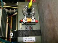
– Charles Guan July 23, 2015 last minute addition - an “anti-fuck” diode, pointed against battery voltage, for allowing regeneration current to pass back through in case the fuse blows. No automatic alt text available.
11 Comments 55 Like Comment Comments Charles Guan Charles Guan this idea brought to you last year some time by Phantom, i think. someone talked to me about it anyway 1 Manage 2y · Like Jon Halverson Jon Halverson Highly recommended. It only took us a couple FET replacements to figure out what was happening. 1 Manage 2y · Like Eli Richter Eli Richter Is this needed only if you're using regen braking? Manage 2y · Like Charles Guan Charles Guan like cool kids Manage 2y · Like Jaimy Juliano Jaimy Juliano Jon, where you blowing FETs with the field current cut too? Or with field still powered outside of the fuse? We run our field through the fuse so I figured I was ~safe. Never had any problems until we had all the problems in KC so now you got me wondering. Manage 2y · Like Jon Halverson Jon Halverson Eli Richter Its an issue for us if you drop the throttle after the fuse blows because the controller still has some juice and sees you tell it to regen. Problem is there is no where for the regen current to go, so the voltage increases (ala switching boost converter) until the FETs blow. The diode allows the regen current back into the battery. Manage 2y · Like Jon Halverson Jon Halverson Jaimy Juliano Its a problem either way since the regen charges the caps at the controller and keeps everything up and running. Manage 2y · Like Eli Richter Eli Richter Jon Halverson We don't have regenerative braking on our car, it's just a simple Alltrax axe controller. Manage 2y · Like Jaimy Juliano Jaimy Juliano I think i get it. I didn't think the residual magnetism on the rotor after field current was cut would be enough to generate any significant voltage. I was thinking “alternator” or “generator” not “big f-ing inductor in a big f-ing boost converter”. Correct? Manage 2y · Like Jon Halverson Jon Halverson Field current doesn't ever really stop since the regen keeps the supply caps post fuse charged up. up too much is the problem Manage 2y · Like Jaimy Juliano Jaimy Juliano Got it Manage 2y · Like
Batteries
Mike Reilly July 6, 2015 Next short survey: what's your choice of battery? The brand and model would be very appreciated. 21 Comments Like Comment Comments Jon Halverson Jon Halverson Phantom48 uses 12S2P LiFePo packs made with 8 Ahr cells from Headway. The older discontinued power cell, thus the closeout deal when we bought them. We add a 250A fast blow fuse internally to protect the cells from a dead short. 1 Manage 3y · Like Tanju Bayramoglu Tanju Bayramoglu currently running 3x 35Ah SLAs from Harbor Freight's “solar panel department”, they're big and heavy. hoping to upgrade in the coming years. Manage 3y · Like Randy Farmer Randy Farmer I have two packs made with 3x18ah UPS batteries, and one pack that are very similarly sized Wal Mart special AGM 3x18ah ATV batteries. Manage 3y · Like Scott Rizzo Scott Rizzo 2 12vx35Ahr simular to Tanju Bayramoglu. Would love to go to LiFePo but dont have the budget. Need a deal like Jon Halverson found. 1 Manage 3y · Like Jon Halverson Jon Halverson Scott Rizzo, It was the 38120P that we found for $9 each. There are deals like that around, but you gotta watch for them. A123 pouches are what we really wanted to build with, but the market on them at the time was not good. Our packs are $216 each,…See More 1 Manage 3y · Like Scott Rizzo Scott Rizzo I've seen the video of the snowblower and mower. Very cool use what you have learned with the car. Manage 3y · Edited · Like Scott Rizzo Scott Rizzo I think in the off season I am going to experiment with the alternator as motor power system. I could remove a lot of weight over my 40+ lb motor and maybe extend the battery run time 1 Manage 3y · Edited · Like Jon Halverson Jon Halverson The motors on the blower and mower are nice DC motors. we would have loved to use them for P48, but determined early on they were no way legal to run based on the budget rules. Using alternators was the alternative, and felt like an appropriate chall…See More 1 Manage 3y · Like Scott Rizzo Scott Rizzo If you have some time in Detroit I would like to pick your brain a little on the alt conversion. I have been doing some research but any info you are willing to share would be appreciated. I am sure I will be starting with off the shelf parts just to get it running 1 Manage 3y · Like Chris Lee Chris LeeChris and 2 others manage the membership, moderators, settings, and posts for Powerwheels Racers for Adults. Ditto, I'd love to hear about your alternator setup. Manage 3y · Like Jon Halverson Jon Halverson More than happy to. Get a couple of these to start: http://www.ebay.com/.../36V-800W.../160806898126…. Then you need to find/make something that will put around 3A through the field winding. We raced 1.5 seasons like that, and still bring them to every race just in case. Manage
EBAY.COM 36V 800W Brushless E-bike& Scooter Controller With Hall 1 3y · Like Randy Farmer Randy Farmer Are you using one of these new fancy brushless alternators, or a good old fashioned one? Manage 3y · Like Jon Halverson Jon Halverson I didn't know there was such a thing as a brushless alternator. I forget the model number on ours, but its a stock 90's GM alternator. One has “92 Lumina” written on it. There are pics around. The field magnetizing current technically flows through brushes, but its low current and not commutating so technically its still considered a “brushless” motor. Update: CS130D is the alternator model. 2 Manage 3y · Edited · Like Scott Rizzo Scott Rizzo Looked up the part on eBay. Is it possible to run on 24volts or does it need to be 36? My battery packs are 24v now and I am not sure I could fit an additional battery in the car Manage 3y · Edited · Like Jon Halverson Jon Halverson Charles Guan has some tear down info you should read. Look up Jasontroller. Manage 3y · Like Charles Guan Charles Guan we couldn't get my van's alternators to produce torque worth shit. must be a “big muscular U.S. mancar with big muscular U.S. man-ternator” thing 1 Manage 3y · Like Jon Halverson Jon Halverson We started with static torque tests to see what current ranges worked best. We fed one phase and used a torque wrench to see what it took to break it over. We were able to see the field saturate, but never did find the limit on motor current. At 150A its hard to do a stalled test without smoke coming out. Manage 3y · Like Jon Halverson Jon Halverson Charles Guan are you sure your field winding was working right? The alts will spin just on residual magnetism, but really low torque. Manage 3y · Like Randy Farmer Randy Farmer So how well do the run at 80/60/40 amps? I'm intrigued now Manage 3y · Like Jon Halverson Jon Halverson this thread is getting long… We won a stack of medals with two china controllers limited to 30A each. That ended up being just about perfect for the 40A fuse. That's 30A battery current., motor current can be much higher. With our own controller design we have more control over things, but the 40A fuse keeps it from being a huge advantage. When the power into the system is limited like it is, a fast car has to be an efficient car. We really need to build a dyno…e 1 Manage 3y · Like Mike Reilly Mike Reilly Thanks again folks, more short questions to come. Manage 3y · Like
Greyslake garage, Hall Install
This is not necessary if you're running sensorless or use a shaft mounted magnet and a magnetic sensor (ala Phantom 48 and Phantom ICT)
Grayslake Garage - CartastropheLike Page July 20, 2015 · I just went through the process of installing Halls in the MK III alternator. Since a lot of people in KC asked about installing Hall sensors, I thought I would share a photo guide. I should do an instructable, but if I never get a round to it, then the info never gets out. So, here ya go.
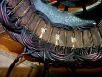
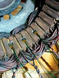
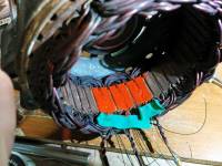
- Step 1: Grind out some “Hall holes™” in the stator with a Dremel and a carbide burr. Try to find slots that don't have windings to close to the surface. If you can't, just get another alternator (or the front half and stator from one) they are like $10. On the MK III (pictured) I have a Franken-nator because I had a front half that had room for sensors and a different back half that had good brushes and a new bearing.
Jon Halverson Try not to short the laminations during this process. There may be a way to etch back a bit with some salt and vinegar. Manage Like · Reply · 3y Grayslake Garage - Cartastrophe Grayslake Garage - Cartastrophe Yeah, good point. I was worried about that the first time I did this but nothing bad “seemed” to happen. Maybe we'd be twice as fast if I wasn't always creating wild eddy currents in or motors ;) Manage Like · Reply · 3y Jon Halverson Jon Halverson likely just a little extra heat. probably not a big deal, but this is racing!
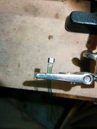
- Step 2: Add some small “whiskers” to the sensors. I use some enamel coated wire.
- Step 3: Insulate solder connections (I used a little Kapton tape, but other things work) and glue into place with some super glue.
- Step 4: Slather the things in “red insulating varnish” (search McMaster).
- Step 5: Join the 3 VDD wires together. Join the 3 GND wires together. Wire and shrink tube those and the 3 OUT leads to the wires that will exit the alternator. Tidy it all up and put the thing back together.
- Step 6: Profit.

